


Lane
-
Posts
1,042 -
Joined
-
Last visited
Content Type
Profiles
Forums
Downloads
Gallery
Store
Everything posted by Lane
-
I'm really pumped up by this one day lower build. I've had this sitting around for months; I don't know why I waited so long. It's quiet hours right now, but I'm planning to go out shooting with my morning coffee. It's going to be very windy; but still worth testing the shot timer with quiet .22lr, and whatever else I feel like dragging out there. Certainly going to put a few more 7.62x39 rounds through as well. Looks like the Pelican 1750 long is the way to go for rail travel; it has an interior size of 50.5" × 13.5" × 5.3". That should fit about 50 pounds of rifles without too much trouble. I don't see why I can't finish a .260 before fall. I don't know what I should bring really; having never been to a fall shoot before... Got back in to the shot timer code and just about to add decimal points to the recorded times, and increase the resolution recorded to include the tenth of a ms. My to do list is getting quite short. I need to add a few routines to help me profile my code, and look at memory in real time. I was just reading about a cycle count variable I wasn't aware of; and that can help with timing accuracy by counting instructions instead of microseconds. I had my timer in the truck with me the other day while running errands and noticed it rolled over the microsecond counter. Apparently that happens after 71 minutes, and will write negative time values to the file if it does. I'm not sure the best way to get around that besides a timed sleep function. My only concern is; what if it's running a course at that time? I could do filtering to look for that; but I would also have to count how many times the counter rolled over for very long sessions (like running all day). Seems like a pointless exercise; but there are a few cases where I can see this happening at something like a fall shoot. I did a search earlier and found a few threads with polymer80 .308s. Nobody complained; but I didn't see any long term reporting either. I don't plan to use polymer lowers for anything violent; and I would worry about my current .308 on a polymer lower. On the AR-15 side; the .22lr CMMG doesn't even use the buffer tube, so that seems like a good choice. My 7.62x39 is also a very tame gun; so why not? I haven't weighed it yet; but it feels great even with an aluminum lower. The balance is spot on right now, so I'm curious to see how it feels with something lighter. I've dug out the LPK, buffer tube, and buttstock to finish this lower. Only a few more hours and I can assemble it at sunrise.
-
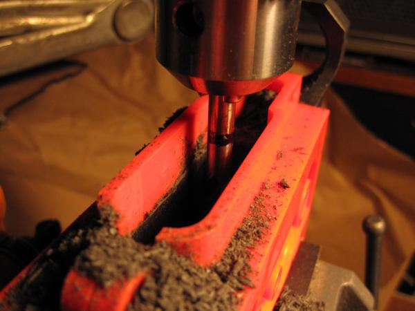
Alright; I will do that. I'm well aware there are things I don't know, and haven't tried. While I don't like the giant lips on the jig; I'm really am impressed with this polymer lower. It mills so fast, smooth, and quietly; I'm well over 75% done. I think I could finish one in half an hour if I tried to do it in one sitting. Honestly going to need at least two more of these; though I'm still not sure how I feel about using one on a 308. I don't recall seeing anyone else around here with a polymer80 Warrhogg build.
-
I've been eyeballing those pistols lowers too. From a legal perspective I would need to get a pistol permit, which takes forever here and isn't exactly guaranteed. I did read somewhere that you can't be denied for a premises only permit though; which is totally fine if I'm making my own. I would really like to do a 1911 from scratch too. I have a friend in NM, and really enjoy being the southwest. I'm started to get more comfortable with the twisted gun laws here; though I would prefer they were repealed for upstate residents at least. Besides having no chance to play with a full-auto, I don't see that I'm missing all that much. There are a couple of oddballs though; like I can't build an Uzi with a 16" barrel, because of where the magazine lives.
-
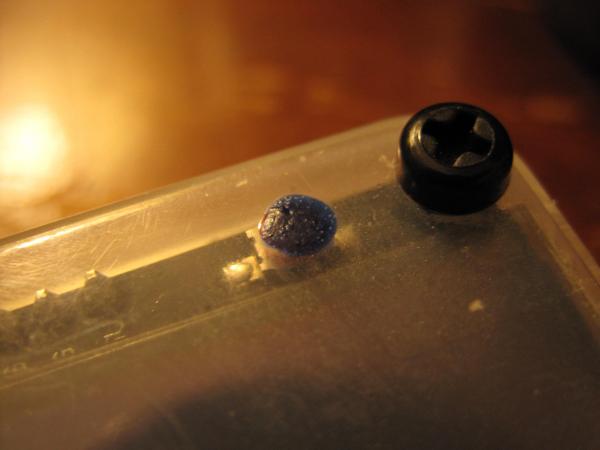
Decided to take a short break on the timer software. I will probably revisit it later tonight; but in the mean time I want to get started on another lower. The jig that comes with a polymer80 is much taller than what I normally use (but the lower's profile doesn't fit in my regular side plates). The mill bit it comes with it also useless in my setup because of it's length. I'm impressed at how easy this material is to mill (it's my first polymer lower), but it does smell a bit strange. I think I'm better than half done and have only been at it for about 10 minutes. I upgraded the button location markers with some temperature sensitive "blueberry" paint; it turns bright blue when warm. Also ordered three doppler radar modules to test; not because I'm sure it will work to measure bullet speed, but it's something to try. One of them in particular looks like it might be made to function with an antenna modification.

-
I've been considering this quite seriously. I took an Amtrak all the way around the US a few years back and it was an absolute blast. Looks like they'll carry up to 50 pounds of guns; and legally I should be good to go as long as I stay out of New Jersey (totally fine with me).
-
None that I'm aware of. I'm just happy to be over the hump on this project after who knows how many hours writing the core code. Obviously I've enjoyed some other threads around here along the way; like the gun pusher chronicles. But I really have no idea about this blueberry thing. I was simply poking fun at it, and making light of the fact that I was using rejected nail polish to mark the otherwise mostly hidden button locations.
-
I don't think it was a div 0. I've never done that in this code. Out of bounds maybe?
-
I don't know what you mean; but I've been looping for decades. Does blueberry touch? Or can it touch blueberry? Is that more like an out of battery experience?
-
You don't know what I don't know; and I don't know what you don't know either. True or false?
-
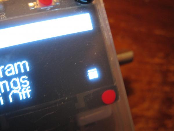
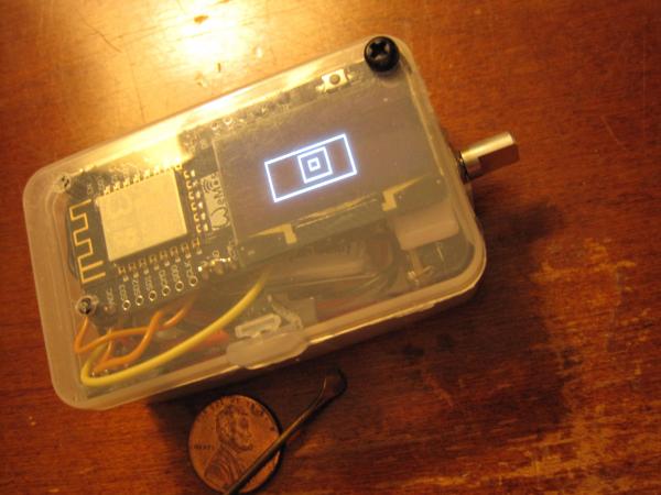
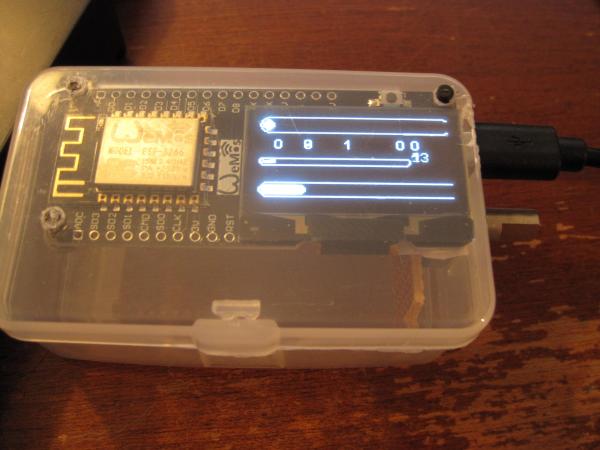
Had to use what I have on hand for this first build. This nail polish was a reject when I was told to go buy nice colors. Maybe next time I'll choose blueberry... Turns out there is some nice temperature sensitive paint in the house. I'l be sure to paint this second build buttons with those choices the next time around. There is also a new "icon" in the bottom right corner to indicate when you can press on the screen. After the lady in the house tested the unit, it became clear that I needed to bone up on the UI. Who doesn't think this will make spring shoot?
-
I had written some shot peak detection code very early in this project; and it showed up again in my recent debugging. Turns out that it works really well if I use it correctly. I should be able to use that to hone in on the actual shot instead of the audio trigger time. Then I could calculate a few extra variables like distance and tune my results. I also analyzed the audio file from my original .308 recording, and saw about 20ms of loud sound. All of that is going to need some further investigation but I think I can prove out some pretty sick resolution with this unit. I still need to test things like subsonic .22lrs (they don't cycle my CMMG BCG). I also have no access to a suppressed firearm; but in that case, you should be able to velcro the unit to the barrel. I appreciate all your help and support along the way. All of you around here. Somebody has my .308 headspace gauges by the way... What's up with that?
-
I shopped around for chronographs today and was kind of disappointed by the specs on everything but the doppler radar unit. After looking at building my own doppler radar unit I came across someone else who built an optical unit with a 24" separation for accuracy. Cheap commercial optical units are +/- 0.5%-0.25% accuracy; that's not enough to test powder charges at the single kernel level. I figure if I build one on a 10' 2x4 with reasonably accurate measurements I could get close to what I need to measure single FPS in a load. I'm not going to be buying a commercial unit based on the stated accuracy right away. I may need one later to compare my results though; and that is most certianly going to be a doppler unit. I'll order up a cheap doppler radar module and see what happens; but I doubt it will work at all. Wouldn't be sad if it worked mounted at the end of my barrel though. Those magnetic chronos look kind of neat; and claim accuracy. But really; that's nothing more than strapping special electric guitar pickup to the end of my barrel (with a dumb microcontroller of course).
-
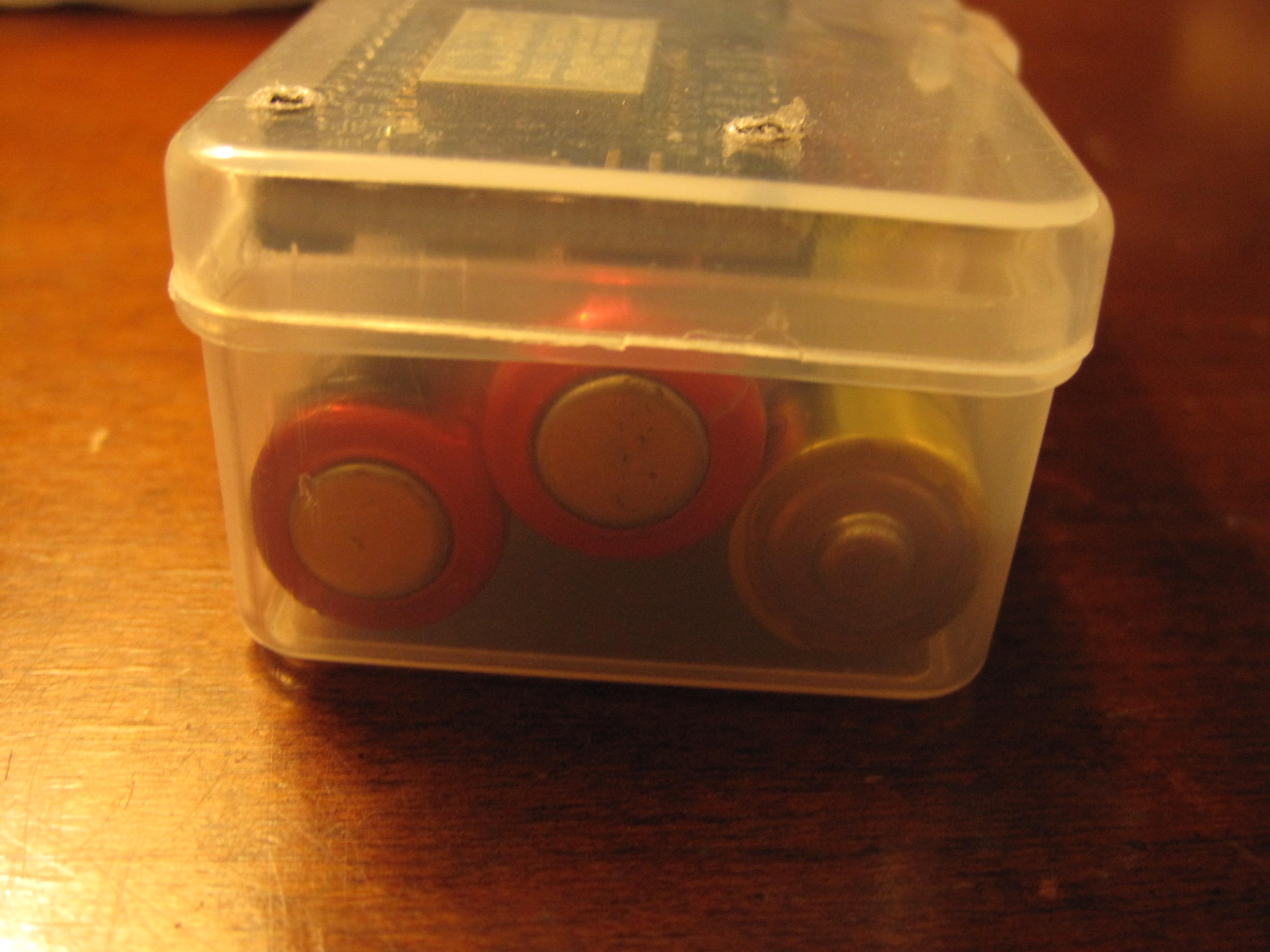
Not much of an update; but the AA battery test came out to 10:49:50; so a hair under 11 hours running non-stop. I would call that good enough; and expensive lithium AAs would likely last even longer. I'm not 100% sure how to mount the batteries in this current type of case. I'm considering cutting access holes and epoxying battery holders to the two bottom edges. I could also drill two holes in the end, but would have to fabricate some kind of door for that to work out. I could just stuff them in the box like my current build; but then I would need to add a different kind of charging circuit to the mix which I don't have on hand. I added a highlight to the currently selected menu item. I also added display writes to the loop when a shot is heard since it doesn't impact performance. The rotary encoder now enumerates one click per mechanical detent. It outputs two cycles for every detent so I had to filter one out. The shot timing display screen is still a little sloppy; but I will work on that more now that it writes updates in fast timing mode. I have been considering a vertical display mode; but won't likely approach that right away. That is the kind of that that can be fixed in software alone; but adding an accelerometer in hardware isn't out of the question either.


-
Ran into a brick wall last night, and hadn't been re-versioning my code much. Found a hard crash when scrolling the menus for no apparent reason. The last version that worked perfectly was 36 hours old. Copied and pasted the functions from old versions, and still couldn't make it work. Even after sleeping; and using the undo command ad nauseum, I had no resolution. I had been running around with a baseball bat inside my code to clean things up; which is what brought about this problem in the first place. Even broke the button delays I had programmed a while back too because the main loop was running "too fast". Button presses were showing up as long button presses instead of a short because everything is faster now. The menus didn't look as smooth after clocking up to 160MHz; so I wanted to revisit that before finishing out those last bits of the user interface. I thought it would be more fun to test when everything was animating smoothly... The thing that pissed me off the most was; the menu display function is only 70 lines long (first loop setup, string array designations, context updates, scrolling animation; and display writes, all in 70 lines of code). I was all over the place trying to turn things on and off as there aren't many options to begin with. I needed a debugger; which took a few hours to download and install. The answer was malloc; I already fing knew it was a malloc from the exception code. I threw a dart at the wall after seeing a pile of 0x00000000 in the memory read operations, and found an array that used to work just fine; but was reading memory out of bounds. These string arrays are used to display any and all menus on the system; and have been working for weeks now. In hindsight, I have no idea why it ever worked; but I'm actively pushing the limits of the hardware from every direction now on purpose. This current version; 0.9.71 again works smoothly and is reliably. There are too many fixes and updates to list right now. I need to upload a full set of fonts; since this current install only has a few sizes between 8-16 (for those with poor eyesight). Also need to rework all the x,y positions of string writes to the display to support multiple font sizes. In testing that earlier code, I had some funny glitches where I turned off a font size change in one place, and some other display function looked all wrong. Simple to implement once I start testing; code calculates font height in a number of display functions already. I can upload any font I want; any votes for small pixel readable fonts? I doubt I can fit more than one or two. I ran in to one glitch when testing broken code where the screen wouldn't update at all. The soft reset button doesn't short out the power source; and wouldn't kill the power to the display. Since I have a "built-in" lithium battery on this unit, I will need to drill and wire a battery interrupt reset button. That was the only way to fix the display without killing the battery; which I still can't recharge inside afterward (complicated poop with complicated poop right there)... The DC/DC converter I'm using is certainly flakey. The AA battery test has issues starting up the first time with the same module; but at least those batteries would be removable to glitch start a unit. Latest 2xAA test is at 9 hours and running; hope I can catch it around the time it shuts off. I don't think I mentioned. There is actually a newer chip in this family that is "better"; and has bluetooth. I just didn't see a reason to go bleeding edge the first time around (for all I know there are 2 or 3 new ones). Looks like those ultra fast 0.005ms reads won't be possible without the FAST ADC function available through the native SDK; but that's installed now. Should be little more than a copy/paste to compile that way in the end; thanks to that GDB quest of course.
-
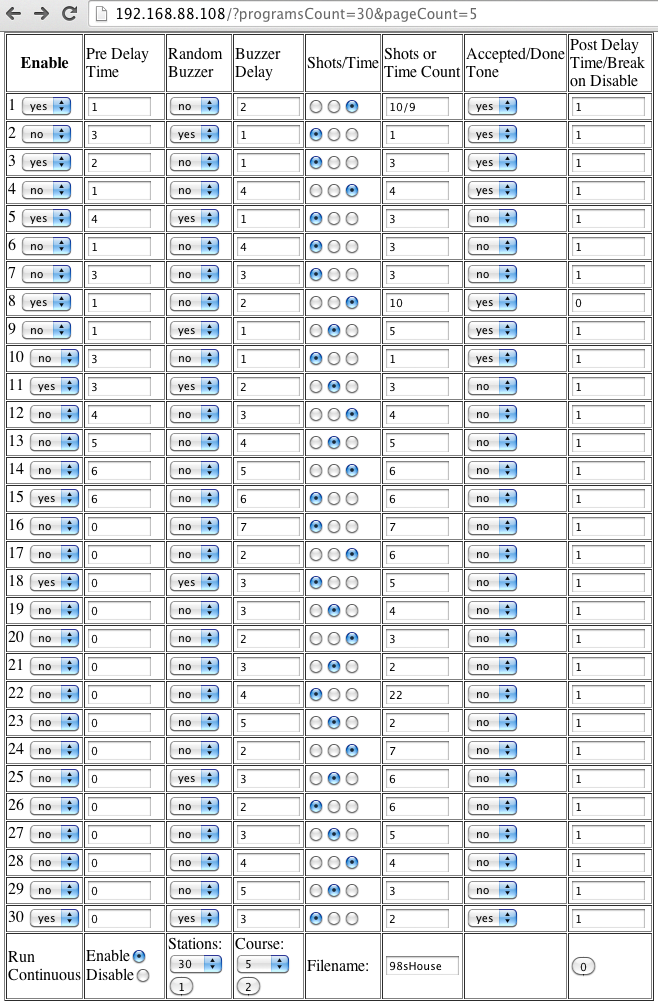
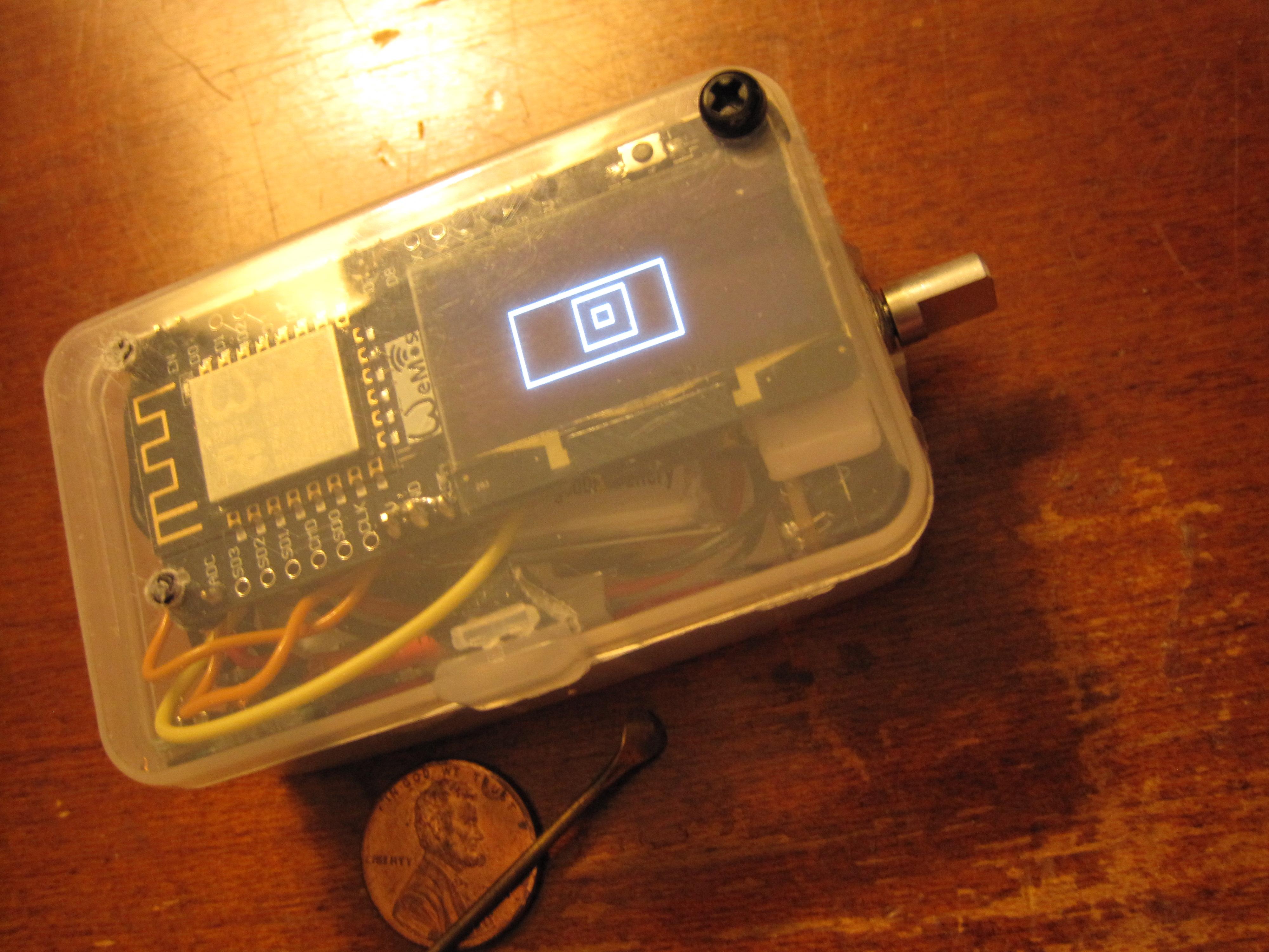
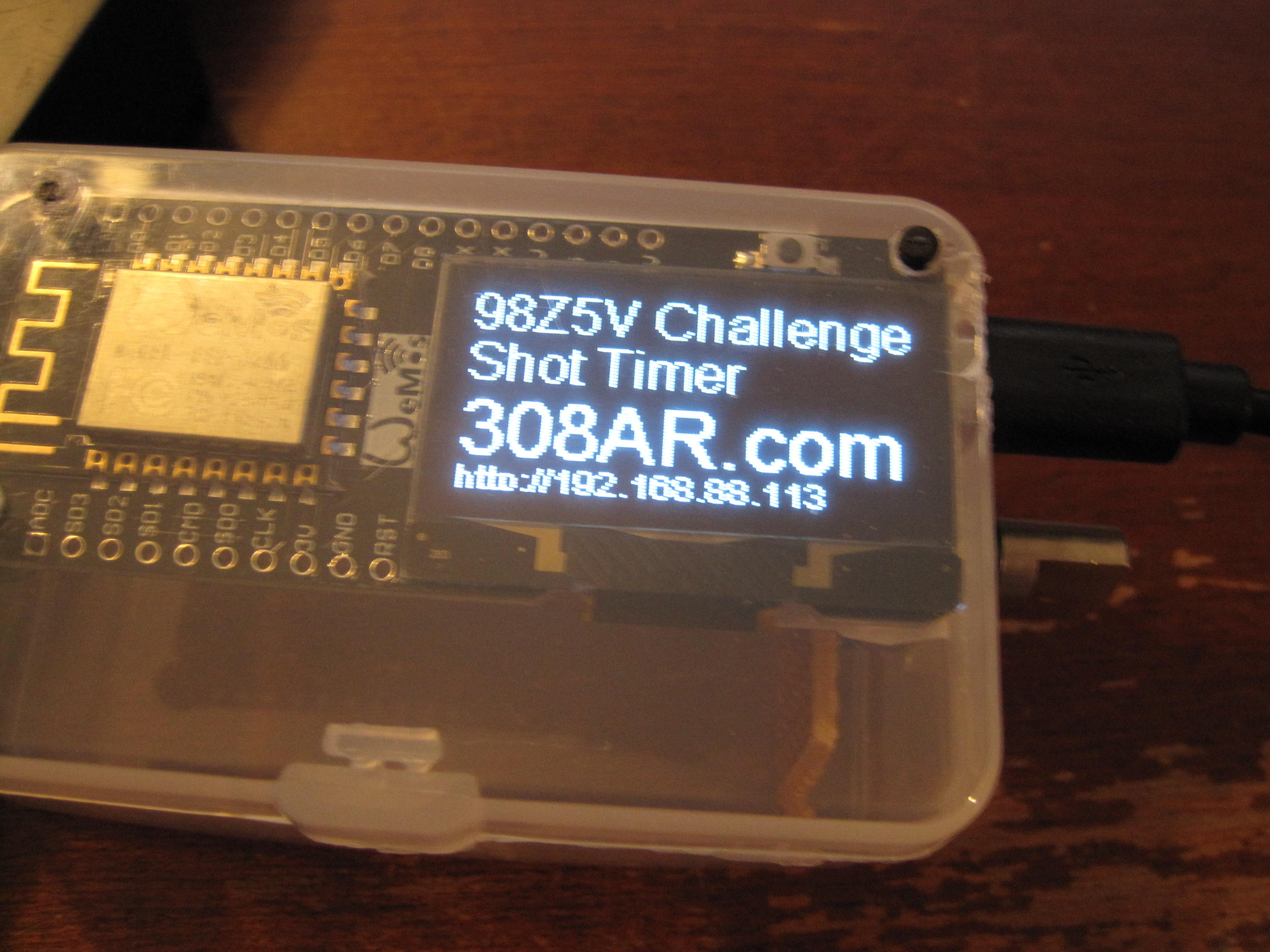
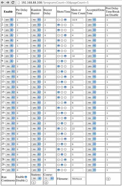
That was honestly the easy part of this build. I used to live with a guy who loved shooting shotgun courses when he was younger. I can't tell you how many times he told those stories; but they certainly stuck with me. I crafted the functionality out of the possibilities I could image being important. I also read reviews of other products to see what those users DIDN'T like. Minimizing the input was also a design choice I think will help make it easy to pick up an use without a manual. It works much like an old iPod in terms of control simplicity. Pretty burned out after finishing most of the programming webpage. The last thing to do is parse the data back into the HTML form from a text file when the page first loads. I'm not sure how much further I can go; but I was able to post 30 stations over a slow WiFi connection. I may be near that limit depending on how much POST data I can send in real life. Some other users complained about 2k being a limit; and I'm getting close to that. I can live with 32 if that turns out to be an issue; you could create (presumably 127) pages of 32 station courses in that case. Here is a screen shot of that config page which is basically finished. The actual post data has very short identifiers to save on transfer size. Hybrid timing of either shots or time is now included, as well as a text course name to display on the screen. Turns out the fast timing mode can still display things on the screen; they just don't update in real time. It seemed weird if the display went completely dark while the unit was running... In my current build I just drew some rectangles before turning off the display writes for fast timing mode. Should be able to draw the normal display one time just the same; and update once again between each station. I'm not even going to try to write display updates while the shot rings out; that can wait for a future update. Maybe one or two more brutal coding sessions left.
-
Transistors showed up, so I can finally finish hardware builds with an amplified buzzer. I got the WiFi/webserver to toggle on and off without crashing the microcontroller; and the credentials are stored in the settings file (not hard coded anymore). I'm pretty much down to course programming and populating a few more settings menus with actual values. Both of those items are nearly finished but I had been trying to make everything as efficient as possible. I had been stressing over the course length differences per page; but as I sat here writing this I realized I can simply use separate files for each page. That eliminates the need to preserve the rest of the programming file when editing, since there is no way to reliably insert data in the middle. I can only add to the end, or rewrite the file completely. I tested out the fast timing mode (no display during shot timing), and got it down to 125us per sample. Looks like the theoretical maximum is closer to 5us per sample, so I might be able to go deeper. Quite frankly I'm just fine with an eighth of a ms for the time being. I haven't retested this with the WiFi off, or reviewed my button polling code to see how far it can go yet. Screwing around with all that I had to change all my timing code to measure microseconds instead of milliseconds; that made my shot file size balloon quickly. I rewrote the format of the file and currently drop the 1/8th microsecond difference. I can fix that easily; but I haven't yet figured out how to insert decimal point in an elegant way. The extra 1/8th to 1/10th microsecond only comes in to play with this fast timing mode anyway; so I may need to simply write a separate format just for that data. Finally got around to testing the AA battery runtime (with old code for comparison to the other times). At first I thought all my DC/DC converters were toast because it wouldn't power my breadboard build. Turns out something in that mix draws too much power. The new style module with display runs just fine; but stopped running when I wasn't paying attention. Something less than 15 hours of constant run time on a pair of 2200mAh NiMH AA batteries.
-
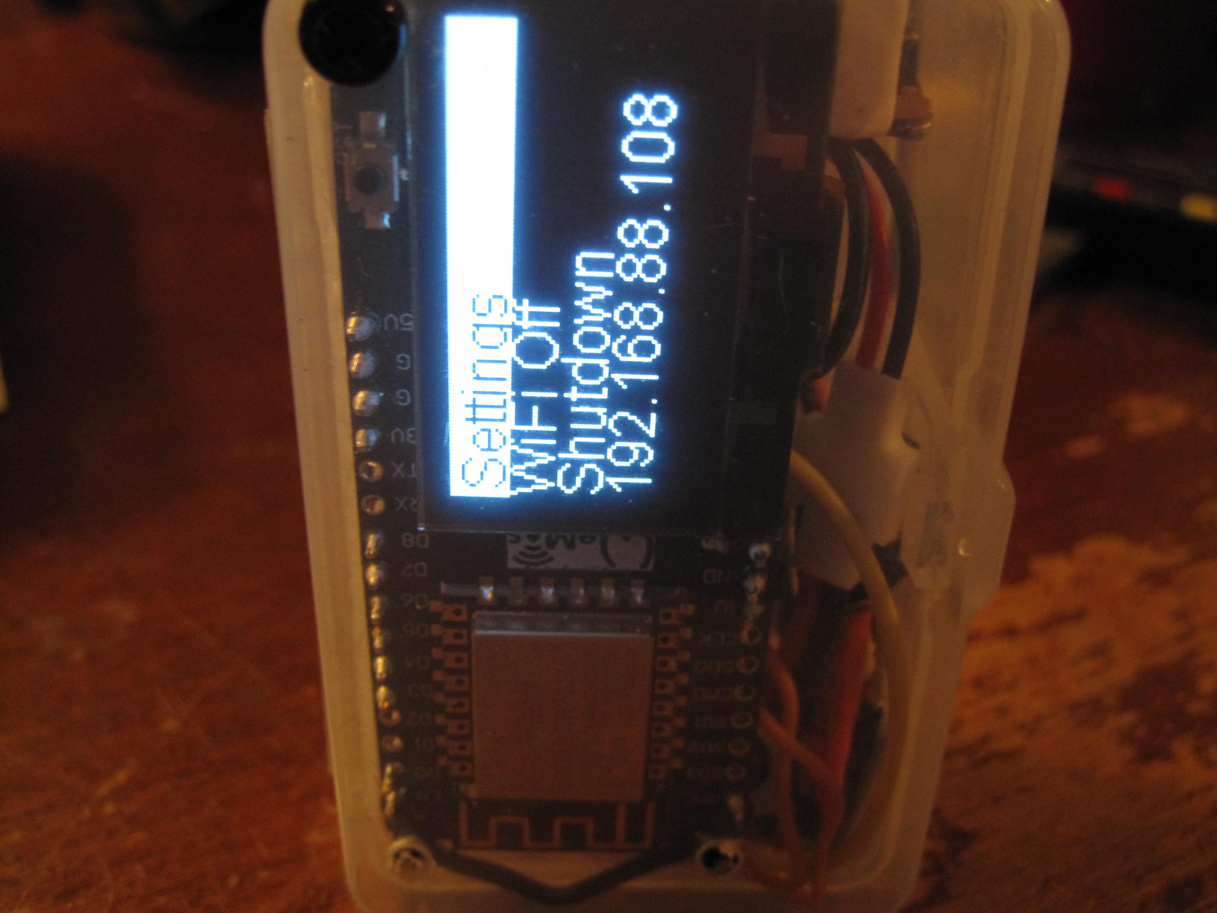
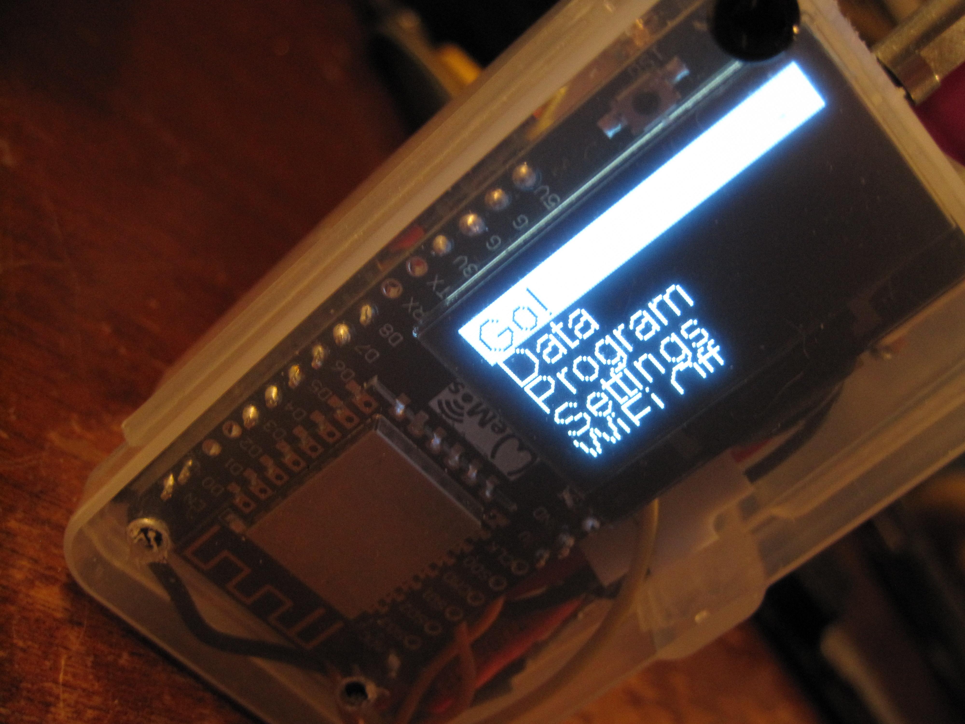
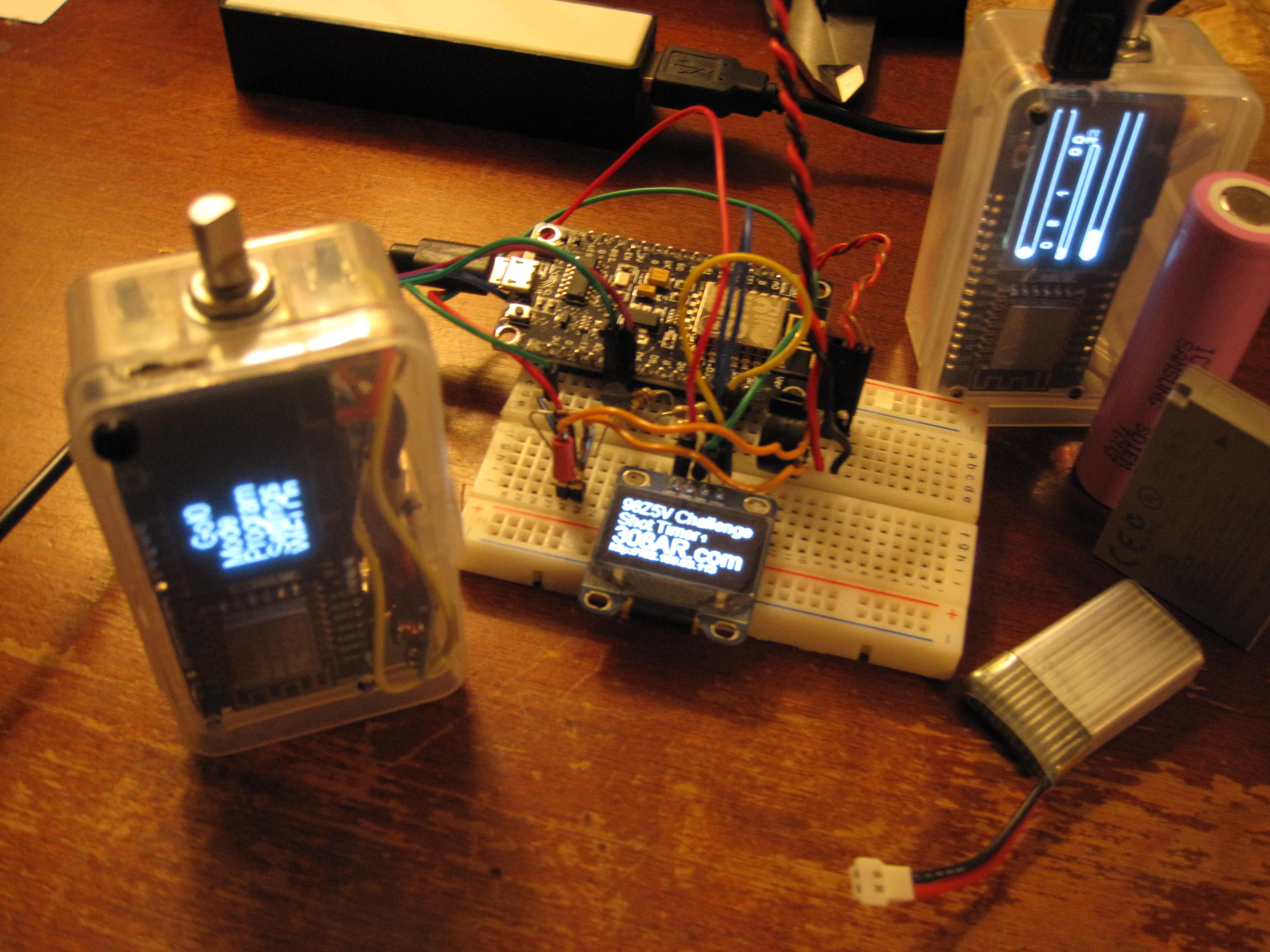
I pulled an all nighter working on the code because I didn't have any other pressing matters here. Got quite a lot done; and the device is unchained now. I had been doing all of my development in a demo loop for efficiency; and that has been fully disabled. The rotary encoder and buttons navigate the important functions, and allow the user to press "Go" and start recording shot times. One press of the encoder button cancels shot timing, writes the data to file and displays the times on screen. One more push drops back to the main menu with "Go" selected again. The shot timer screen can also timeout by itself or with a program as needed. This is simply the "infinity" mode that isn't going to be available to users outside of running debug mode. The shutdown command puts the unit into deep sleep, which should allow the battery to last for months; red button powers it back up. Have a bit more work to do processing button presses for every single menu item and mode. It also support holding the button for a long press; but nothing is using that particular feature yet with either input button. I've begun to revisit the shot course programming webpage again. It now streams the file to avoid running out of memory when generating the enormous amount of HTML required. It's still not perfect but I can get 24 shooting stations with some reliability, and occasionally better than 40; my goal here was 127 so I'm making progress. It might simply need to be closer to my WiFi access point for a higher data rate; I am testing at the other end of the house right now. I ran yet another battery down and nothing I did would make it charge in circuit. The voltage was 2.82v the next day; so it didn't discharge it too far. While I was screwing around with all that; I had an epiphany... Why complicate sht with complicated shiit?!?? Two AA batteries fit inside the case; and would remove the need for the lithium battery charger board. Should get better run time too. The only thing I'm not absolutely sure about, is how efficient the DC/DC converter is in that voltage range. I'll hook it up on the breadboard build and test the idea later on. Code is currently at version 0.93; should be fully functional by version 1.0, or maybe 0.98 if I'm lucky. Anyway; not too much longer on this project. Still have to wire up a motorized trickler when those new scales show up (should be any day now). Also turn out some solid copper projectiles on the lathe just for the fun of it... Then I can close up this thread.

-
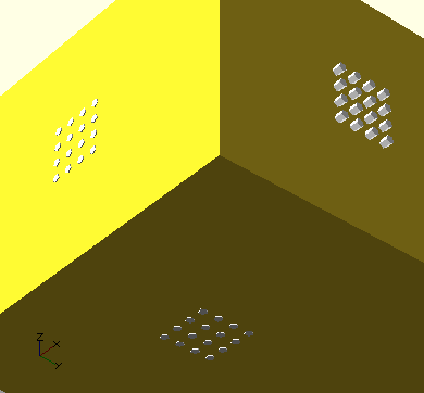
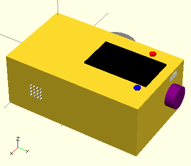
Nothing new in terms of the battery charger situation. The battery build is working fine when I don't let it die completely, and I've been testing it regularly. I had a new thought about that particular problem, so I'll check on that next time I open the enclosure. Two batteries fit well in the newer build; so if I'm careful with my wiring it should be an 8 hour unit. I looked into buying more CPU/display boards, but the seller is away until Feb 14th; chinese new year I assume. I was surprised that I couldn't find anything like it for even twice the price. That's going to have to wait; and means I won't be working towards a 18650 battery build anytime soon. I will need to work with the parts on hand, and figure out some other elegant solution to the dead battery issue. I don't see any mention of brownout detection onboard, but could design a circuit to signal a digital pin on low battery; if I absolutely have to. While looking for parts here, I did come across a development board which I thought might hit ns timing resolution. Such a thing would simply be used as a co-processor to the existing build. Then I read the specs to make sure it was worth the effort; not even close. Fast CPU, with a slow ADC. I did finally reign in on what would be required just for the fun of it; over at DigiKey the best price I found in single quantities is $65 for a 1GSPS ADC. Read the datasheet for that and found it needs 650-700MHz clock which is out of the question. It was an interesting thought experiment; but not something I will consider for the 50-100x difference in resolution. Have not found my stock of wire, but did recover enough to complete the next build. I also can't find any more BC547 transistors to drive the buzzer, so I had to order another bag. I tried everything else I had in stock but nothing was suitable. These are also the very loudest transistors I've tested; so I didn't put much extra thought into the matter. The hardware, once the battery issue is resolved is basically complete now. I did add a few capacitors to the final BOM; but my total is still something like $14 a unit if you don't include the battery cost. Prices for those parts are $3 for single 4 hour battery, $6 for 8 hour pair; and $7 for 27 hour 18650. If I could buy more boards now, that choice would be obvious; the charger already supports the big battery. These initial prototypes will unfortunately have lesser specs. I decided to update the CAD drawing one last time. This one has the bumped encoder position to allow for the larger 18650 battery. It also depicts all of the final button locations (for current builds) and the USB port. Finally; grills for the three input devices that will be included in a final version are drawn. These initial test units might only have two of those three audio inputs depending on how things fit in the poorly designed interior layout. Centering the rotary encoder in those initial designs seemed like a good idea at the time; but proved otherwise. I also didn't need any of those extra tact switches I had in the initial build. Red is the power up/wake up button. Blue is the front panel switch, actuated by pressing on the case anywhere in that corner or face; pressing the screen works just fine. Pushing down on the rotary encoder is other user switch. I presume Blue will be the go button; but Go is also a menu option; so I'm not sure exactly how my layout will work in the end. As I spend more time with these builds I'll decide for sure. That's entirely configurable in software of course. Assuming I have enough free time; I should be able to release at least one of these into the wild in a week or so.

-
I've gotten most of my small, known bugs worked out. Most were single character changes to the code that I had already figured out by playing around with the unit. I also installed a paper shim in the original battery build to actuate the second button. Tried a half dozen different layouts in the initial build and couldn't make two batteries fit. The header pins I soldered on the bottom of the main board protrude too far for any kind of stacking. Some of the button code isn't quite right; but that's not my biggest concern anymore. Code nearly fixes itself if I think about it long enough. Seems like the battery regulator/charger board isn't working properly; or the battery has its own protection. When I run it completely flat I can't get it to charge again in circuit. I have to open it up, remove the battery, and connect it to another charger. Might be almost 0.1v too low in full discharge; fixing that would likely be replacing a tiny resistor on the board. I have tried quite a few batteries already. I'll assemble the second unit soon and inspect them both carefully side by side. It's not a big deal to order a replacement, or modify the board if it's out of spec. I did get a 10 pack of dumb lithium chargers (no battery protection chip); so that might be a solution if the existing boards won't work at all. If I don't discharge the unit fully; it has been quite reliable. If I move the position of the rotary encoder inside the case, it MIGHT be possible to fit an 18650 2,600mAh battery. I was kind of mad I cracked this particular case when trimming; and I do need to order more boards with the attached display (to replenish my own stock). That beast would allow for roughly 27 hours of non-stop runtime; quite a bit more if it goes to sleep ever. Many of the new settings were implemented earlier today. Most of the rest of the code changes are roughly like shuffling a deck of cards. I will simply be copying and pasting code that is already running, into different functional blocks to even everything out (so there aren't spikes in timing for no reason). When I know for sure what's up with the charging circuit/regulators; I'll move in one direction or another.
-
Minor update here. I spent a few hours checking different versions of the core code to see where WiFi breaks. I was really hoping to see my button ISRs fire in the process; but that didn't happen. I'm running newer code though, so I get a few new features and a 10% increase in available RAM as a result of compiler changes (more program space too, though I don't need it). I had to write my own ISR code for the buttons which runs in the main loop. At first it was a mess because the button had tons of noise. As I worked on coding a debounce solution the button apparently began to wear in. I've got it down to a reliable two hits per button press which is just fine for now. Easy enough to tune out the one extra, and only execute code off on the second one. One advantage of writing the debounce code is the ability to detect button press length; so it can be pressed for a long time to perform a different function. Didn't expect the button input to be such an issue; that original ISR code was written long ago. I just didn't bother testing because it was supposed to work. No matter though; it's functional now without much impact on the loop speed. I've been running more battery tests along with all the code testing. Also, having to test the button code every few minutes made me work in other improvements and upgrades along the way. In particular the program that runs when "Go" is pressed has a lot more information. It now reliably counts shots on a progress bar. The same progress bar would show time countdown if running in that mode. Made me realize that it might need to be an AND/OR situation though. What if I wanted to run that program for 30 rounds OR 30 seconds; whichever came first? New hardware build is only waiting on wire at this point. I have been using it to test the button code with nothing connected to it. I have a bag of silicone jacketed wire around here that would be perfect for this build; but I haven't located it. I also ran into a case where I drained the lithium battery too far for the circuit to pick back up in terms of charging or powerup. I think it's just going to be a capacitor to help fire up the DC/DC converter; but it remains to be tested. Adding a battery meter is something I've been thinking about; but not yet figured out how to implement. Nearly finalized on the total hardware implementation though. After that, everything is fixable with a firmware upgrade which can be done in the field. I've got some new graphics debug code running. I'm going to have to stop clearing/writing the display so often, and split up my memory writes. I'm only 13ms or less on those long loops (0ms when only reading audio input); but I can get that below 0ms with little effort. Not sure what the lower limit will be in terms of fractions of a ms, but I will try to bounce off of that. If the display is entirely off during the shot timing process, I can get some serious speed right now. Might as well make that a new feature; the olympic timing mode. It would almost certainly need a coprocessor to achieve actual ns resolution; but it's not that much more expensive.
-
4:01:39.57 is what I recorded for the 160MHz run. That's exactly 1.5 hours longer than the 80MHz battery time with regard to any small fluctuations. I think my 80MHz time was actually closer to 2:27:59 give or take. About a 62.5% increase in battery life for doubling the clock speed.
-
This thing has long surpassed the run time on 80 MHz test builds... I had read somewhere a while back that running 160MHz uses less power; but this blew my mind. Double the speed for less battery consumption? Less powder, for a heavier bullet?
-
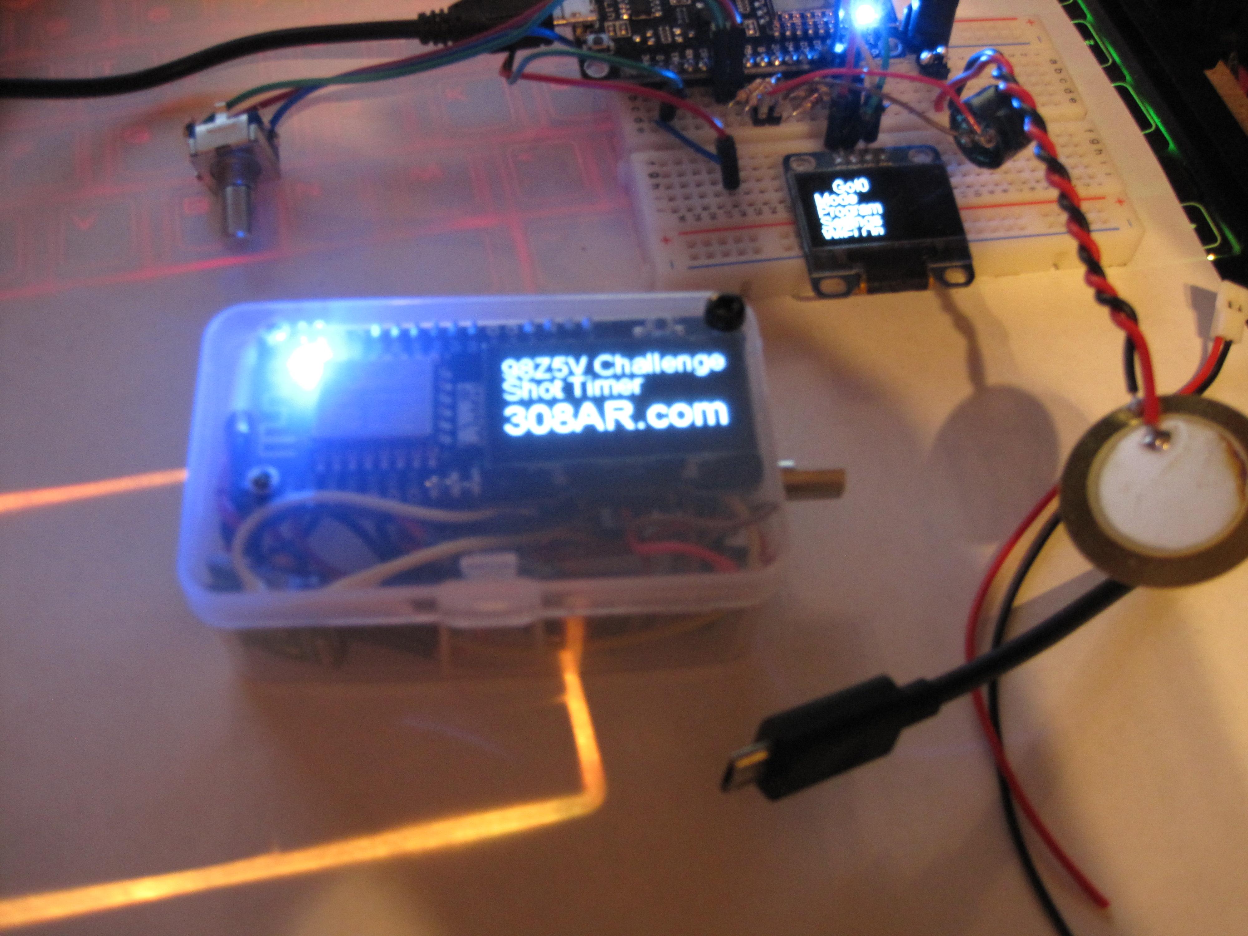
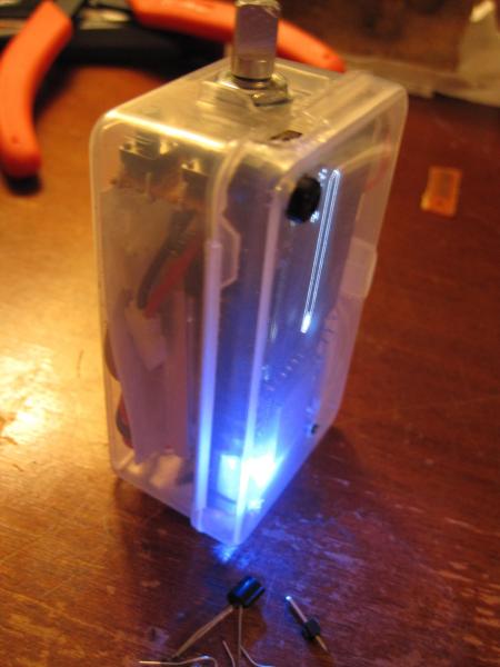
I'm having a good time with this project. As you may have noticed I didn't study commercial products too deeply before beginning my own build. I figured that it would be better to explore the limits of the hardware; than to get distracted by how someone else's timer functions early on. Spent a little while preparing brass for reloading while thinking about what's next on this shot timer project. I put the battery powered unit on a demo loop to see how long the single battery lasts without turning it off; I got 2.5 hours running everything. I harvested the second buzzer and tested them both, with and without transistors. Much louder with the transistor, so I'm going to have to figure out how to wire one in without making a mess. Return from the deep sleep function only requires pulling the reset pin low; and was a single line of code to implement. The reset button can be actuated by pressing on the case above the screen. Turns out the battery dying puts the unit in to deep sleep all by itself. Took me a while to figure that out when the unit wouldn't turn back on even after being fully charged. Started assembling the second unit as carefully as possible, but the plastic box shattered in a few places when I was trimming it. That; and the different rotary encoder position revealed that the FLASH button on the back of the board was usable through the case by pressing on the screen in the bottom right corner. Unfortunately that switch, and the encoder button both fail to trigger the ISR. I have no idea why that is; but it may be another bug in the older libraries I'm using. I can't find anything informative about the problem yet other than a bug report closed because of no input. I've tested numerous boards and checked the circuits with a meter. Debug code even revealed that the circuits are fully functional, and changing the pin status if read manually. I likely have enough clock cycles left to read the pins in the main loop if I absolutely need to go that route (with no functional interrupts); but the rotary encoder fires the interrupts just fine. There is already an animation loop, so this could offset that in terms of timing if necessary. I set up a second battery test with the board running at 160 MHz; and that bright blue LED is finally off. I'll let that go for a while while I work on other software issues. I'm sure the ISR thing will work itself out pretty easily. My current code is well below 1ms in resolution; but I don't know how low exactly. It literally reads a 0 in that field on screen ,so I will have to check it a different way. I realized I need a facility to rename the shot time data file to keep things running smoothly. I knew that the shot data file growing too large would cause problems. This would allow for an onboard archive to ensure maximum performance and use all of the available data storage. This really doesn't happen often; but I've been pushing those limits on purpose. If you download and clear shot data every few months (years?), you'll never have to move/rename a shot file. Looks like firmware can be uploaded via Android devices with an appropriate USB OTG cable (or a computer). I haven't tried it yet, but might as well see how that goes. Reports are that it is a very slow process, but works reliably.
-
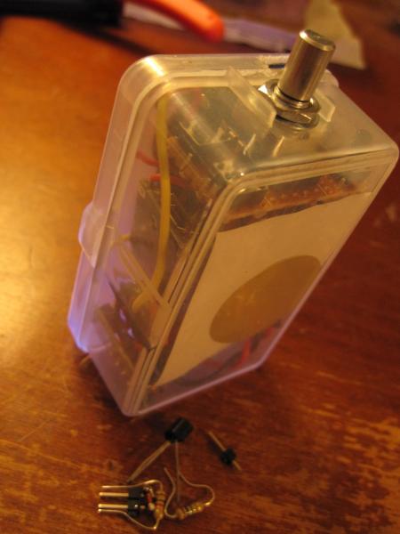
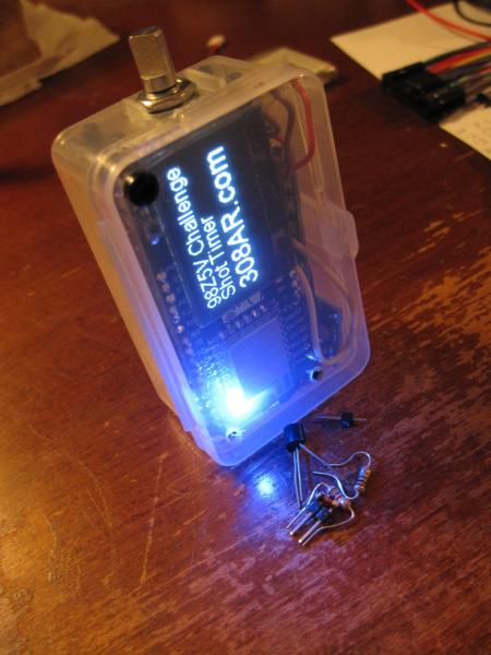
After much fumbling around with the parts and wiring the unit is self contained and running on its own power. I only got one of the two batteries inside it so far; but that should get better as the design is refined. At this point I can actually carry the unit around and test it outdoors freely. It seems like the plastic enclosure is transmitting the vibrations well enough; but I haven't tried a new live fire test. It might be necessary to punch a hole to make it work better; but I won't know until I try with some quiet ammo. I still have a few minor additions to test out before I begin the second hardware build; hopefully building on what I learned this first time around. The wiring in particular needs to be done carefully and with respect to length and routing. Quality wire also makes a world of difference when trying to cram things into a tight space. That alone will make up the extra space for the second battery. I really should have laid out the design first and then cut each wire to length; but at least this current layout doesn't seem to have introduced any appreciable noise (I was most concerned about the power supply). One of the front panel buttons needs to be wired between the Wake and Reset pins to allow the user to wake from the low power sleep mode. At the moment it doesn't have a hardware power switch either so it's always on until the battery dies. It should be as simple as calling to the sleep command, and attaching the two wires for the wake circuit. I'll start testing the wake function on the breadboard build, and laying out my next hardware build as I work the kinks out of this one. I still have to harvest one more of those loud buzzers from a lipo alarm. I found a pin vise though, so that should make quick work of it. One last thing is to run through my code and make sure the front panel LED is OFF most of the time. I find it annoying to see it on inside the case.

-
No external pullup resistor needed. After my last post I got to thinking about the problem in more depth. Seems like I might have had solderless breadboard issues with my earlier build. This problem was only on one of the two pins. I played around with the internal pullup resistors and finally resoldered my whole board. It was a loose pin (or five). Everything is solid and I can begin to assemble the final unit now. Only two external components for the audio input circuit, and two more for the buzzer as needed.