


Lane
-
Posts
1,042 -
Joined
-
Last visited
Content Type
Profiles
Forums
Downloads
Gallery
Store
Everything posted by Lane
-
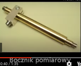
I've decided to dive in to that project for a bit. I really have no idea how it is going to work out; there are a lot of problems with trying to work with a molten metal at that temperature. It is not even entirely related to this project. But since I'm already trying; it might be a candidate for a test electrode moving forward. More power supply modules, and a large battery showed up. I just need to start wiring up terminal blocks so I can mess with this in open form experimentally. One thing I had almost forgotten about here was a high voltage probe for a multimeter; probably oscilloscope too... I just ordered one the other night; so that should be here soon. With a 40kV max limit, I should be able to check the things that matter. These days I'm most worried about heat of the wires during discharge. Generally though; that does allow for higher electrical current flow, to a point... So it might be a blessing in disguise if I don't break any rules (i.e. start a wire fire).
-
Why is this place so quiet lately? I hate to post progress when the news cycle is so slow... Maybe I should post more though. Hard to find primers and all that. Had to clear this off my desk for a while. But just finished ordering all the rest of the parts give or take a few screws and whatnot. Needed a battery to supply huge currents. Check. More HV power supplies; Check two. Someone just ordered up a ring made of Element 75 (on the Periodic Table) the other day. No idea if I can make that happen. I will try though. Once the packages arrive; it's game on again. Just programing up the lab radar, again (that's so annoying; someone should fix that firmware.... Please?).
-
Brownells has more CCI primers in stock right now; many different varieties.
-
Aaaaaaaaaaannnnd they're gone. That was about the longest I've ever see/heard of primers being available in a long time. Usually they sell out in a few minutes to hours. I checked Brownells either last night or this morning and they still had some CCI 41s. Now they are totally sold out of all primers (again). Even saw large rifle primers in stock when I was shopping around; and then they were sold out before I finalized my order.
-
Brownells has primers in stock at this very moment. Some disappeared while I was checking out. Not happy about the price, but haven't been able to buy in so long, I hardly care. SOON I can shoot again!

-
*toast
-
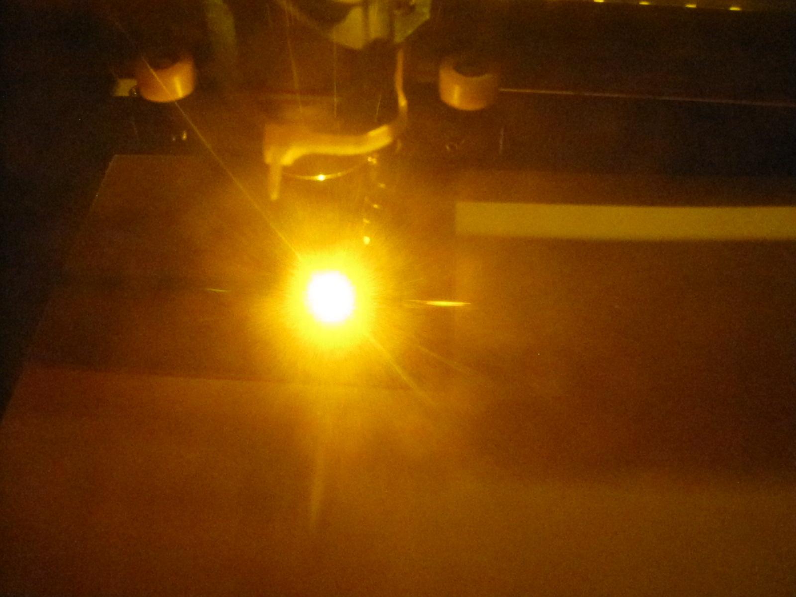
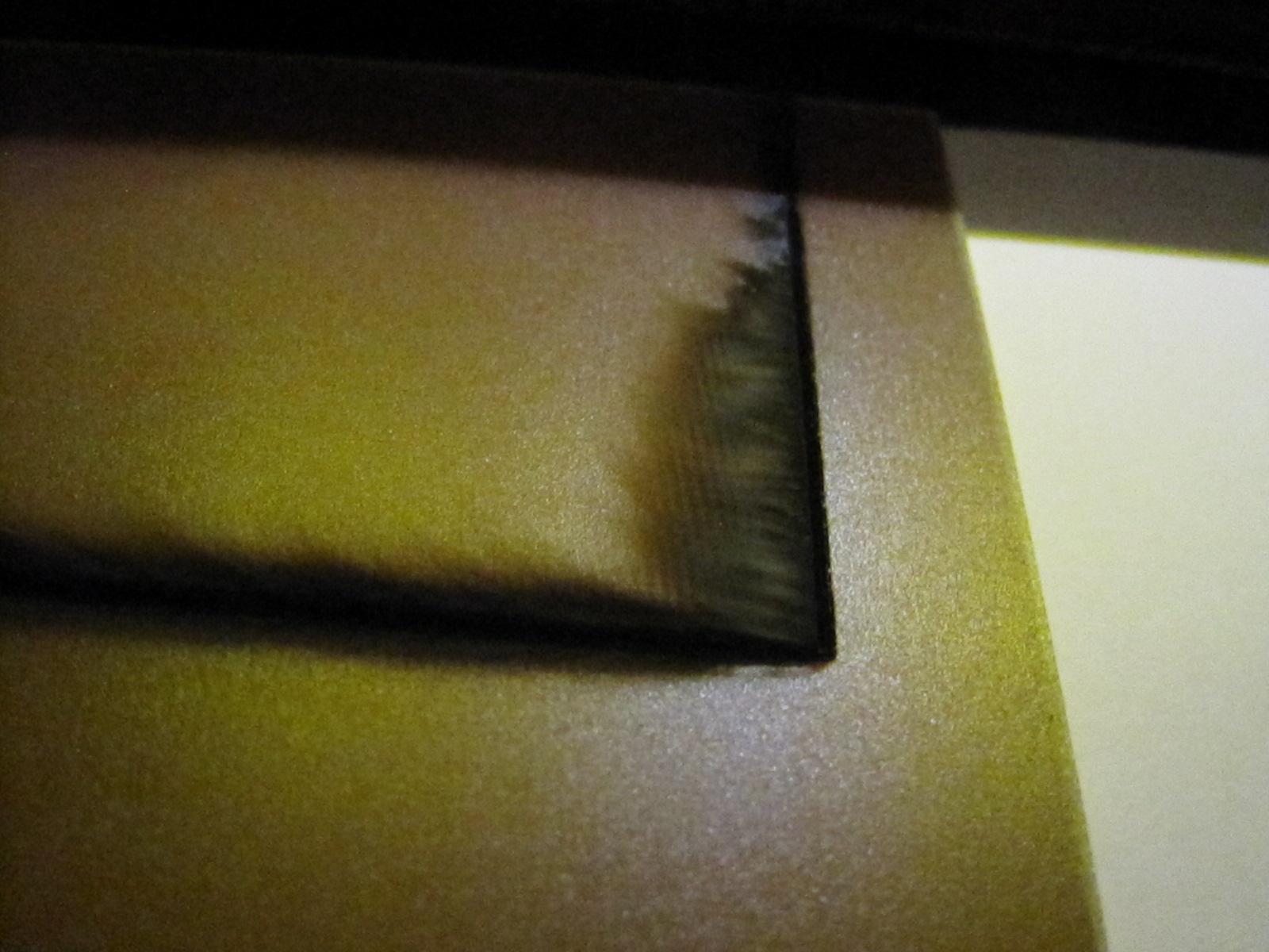
Same here. That's why I'm doing this. Same reason I was doing this years ago when I was in school... Only; I understand a hair more now. At this point I'm able to start looking for points of friction in the system. One of the fist clues (and one I was guessing about a while back); is the reading on the series/parallel capacitor bank. I did my best to overcome all that from the start; but even still... I'm looking at a 93.633803% power on the series/parallel bank; compared to the full parallel set. I'm not willing to poop away 6.5% of my power just to be High Voltage. Again; there might be a good reason to do so; that's why I'm going to try it anyway. Thought some people might like to see real progress. So here is a picture of tungsten-copper electrodes I cut with a hacksaw. Some of them a slightly filed clean; but I can't find a nice file. The closest "cut" is shown factory cut facing up. There's a weird "ring" on those; where it looks like tungsten migrated (heat related?). Two more from a similar project. Cutting FR4 for the first time in a laser. The next few weren't nearly as rotten and burned. Figured out I had to start the cut with pulsed power, and then dig in once the cut line was made. Later cuts didn't look very much burned at all. I suspect these custom made circuit boards might turn up in this project at some point (FR4 is the back side of a single sided PCB (printed circuit board), or the center part of a double sided board. The fiberglass resin that acts as an insulator and makes the board's structure).


-
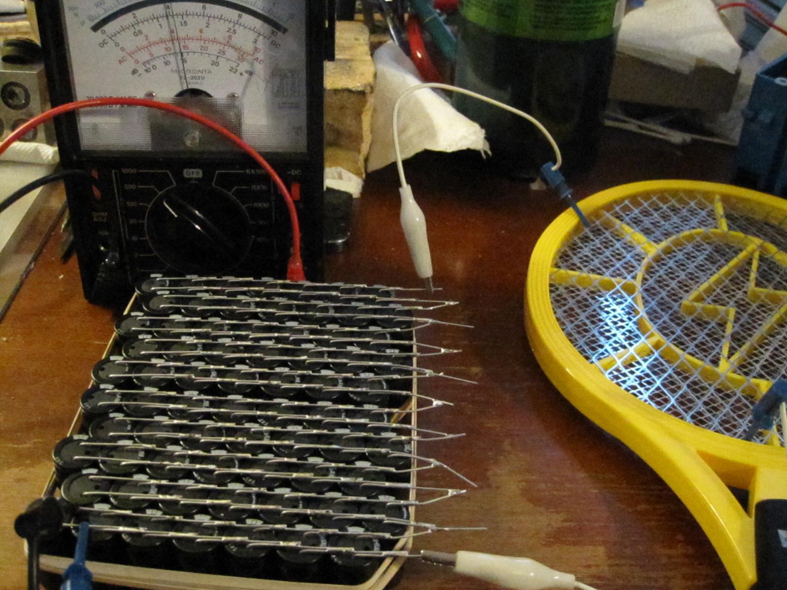
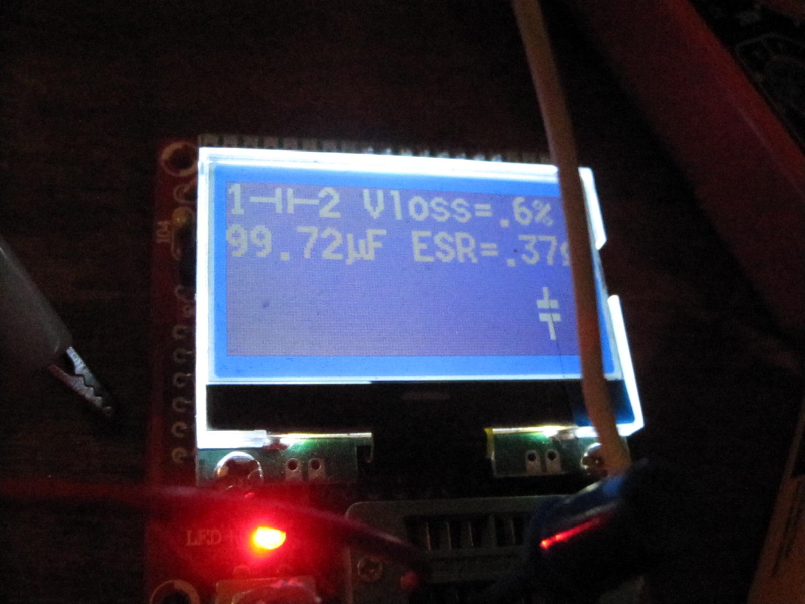
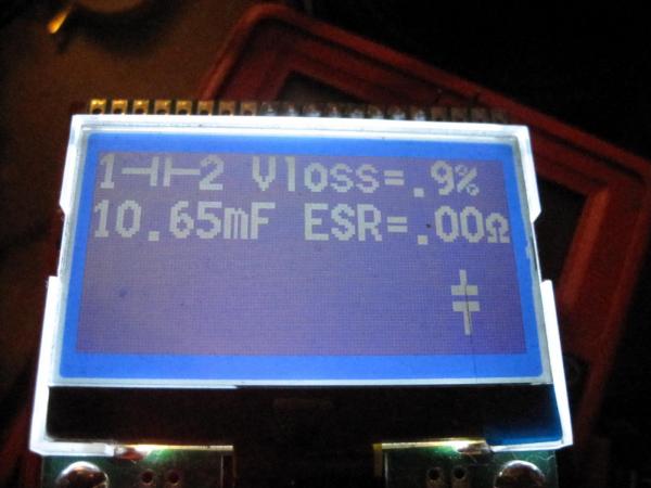
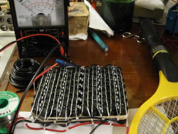
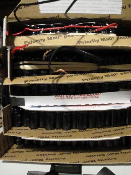
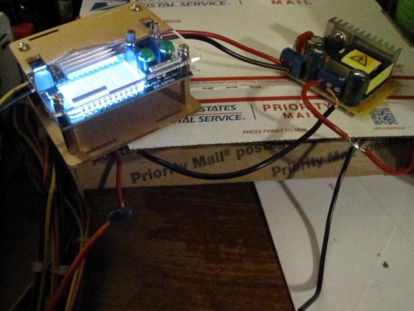
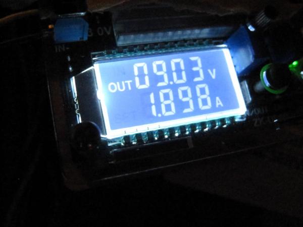
Image update: Series/Parallel capacitor bank charging up to 2,000V off a lithium battery powered electric flyswatter. Charge to just 2/3rds takes about 20 minutes, and kills the battery flat. Could get more speed with two; removing the bleed resistor would help as well. ESR of the Series/Parallel capacitor bank. ESR of the fully Parallel capacitor bank. Fully parallel capacitor bank wired up. The full stack of 490 capacitors in small flat rate boxes. They don't quite fill them up; but that air gap at that top helps me feel better that they won't arc over. New parallel capacitor bank charger. Showing 9V out of the set 12V... I'm drawing more current than I want to play with on my desk; but it can charge to 1/3rd voltage in just a few seconds (VERY fast). With unbound current supply, it could go a lot faster still. Simply trying not to start a fire yet. Have tested the charging and bleed down of both capacitor banks. Just need to set them up side-by-side on the same coil and see which way works better in the real world. I can theorize all day long; but testing is what matters. Just about to clear off the laser for glass cutting. Last image is a drawing of the latest re-design of the trigatron tube. I found a fuse holder that looks like it will give me the best contact area on 1/4" tungsten copper rods. Even allows for a third electrode drilled into the end. The glass will be fatter than a standard fuse between clips; but the contacts will fit the clamp-in holders, and give me the best electrical contact I can find off hand for this scale of device. If the need to get larger; I'll refactor again as needed. Each short piece of tungsten copper will make 3 electrodes. Another reason for the evolution is that I haven't regularly exceeded about 10mm for the total spark gap. Shorter gaps (to a point) will make the triggering happen faster anyway.


-
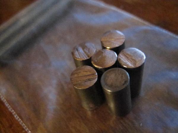
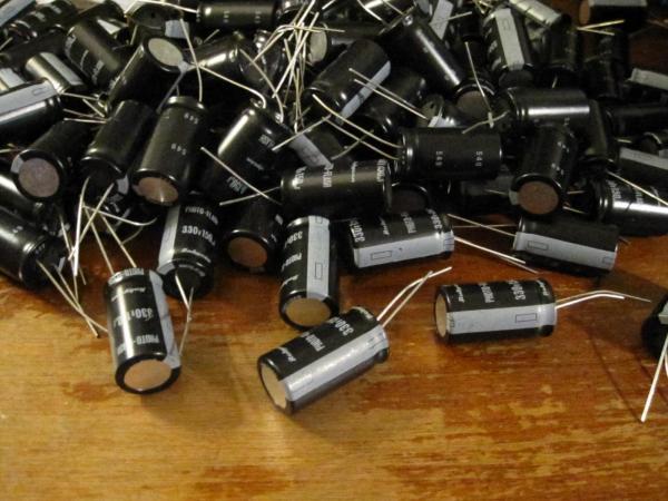
Tungsten-copper rods showed up for the spark gap electrodes. They look a little strange, but it isn't a material I work with regularly; so I can't say if it is normal or not. The centers are pink enough, and I suspect they will work just fine for my needs (unless they need to be larger in diameter). Looking for my hacksaw at the moment. Finished soldering up all but ten of the total quantity of capacitors I purchased for this project. Very much time to get serious with a few baseline tests; and then move forward with a larger testing system. Charged up a test bank to 2kV twice now; and let it bleed off slowly. Since I'm already in the middle of it; measuring the charge, as well as bleed-down time will give me some decent jumping off numbers. Once I get the whole thing wired up on terminal blocks, I'll be able to move things around and run ever increasing tests a lot faster. Still didn't get around to cutting more glass tube. The computer that runs that machine fell off the network apparently, and I have not yanked out the plug to reboot it yet (it is headless; no display). I'd feel better about a way to access it without just yanking the plug out... That said; I still don't have a repeatable process to do those jobs either. The first time I set one up, it was flying by the seat of my pants. I aimed it, and told it to draw a line 6x the circumference of the glass, and let it rip. Did hammer on some pure drawn tungsten rod... Should have trusted my gut. Never made a dent in the rod, and it shattered once I started getting into it. That was fun for a whole minute or two. Feel like I might have done my homework on this one; as nothing has started on fire yet. A few steps later now, and I'm recharging a battery on an electric flyswatter that I used to charge my test capacitor bank. I used a good amount of that battery charge. Just need to scale up battery size, and the charging circuit (for speed); according to those metrics. There is just one more thing I didn't fully seat until now... I could in fact use all the SCRs to try and speed up the projectile pooped out by the trigatron accelerator. The fun part here would be making sure a timed approach could apply; and using the lower voltage DC battery power to make it happen. Maybe a stacked H-bridge, or something banging an induction drive would work. But that's all still a bit too far out... Only to say; I'm thinking about it, and getting ready to start looking at the other end of this problem. The stage two. Pictures incoming when I feel like setting up for all that. (still in the frazzled wiring stage at the moment).
-
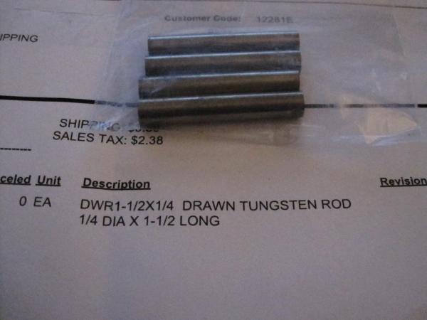
Short update... They sent me pure tungsten rods instead of the copper-tungsten I had ordered. Double checked; I ordered the correct item. And yet the packing slip said drawn tungsten instead. It was pretty clear to see before I even looked at the packing slip. They are grey metal colored, without any hint of pink. Also weighed them; not even close to what they should be (too heavy). I've made contact about the issue, but have yet to hear back. *** Heard back today; they are sending me the copper-tungsten I ordered, and apparently don't want the pure tungsten back. Not really sure what to do with it off hand, but maybe something will come up down the road. I will probably try to do some cold working on a piece, but from what I gather that might be slow going at best. It has a melting point similar to platinum, so it shouldn't be impossible to weld. Finished soldering together another bank of capacitors, and started re-working the previous blocks. I simply wanted to add 1 more capacitor to each of those parallel strips. The hardest part of that was removing the conservative amount of hot glue I had used to keep them together. Might have actually been easier if I had used an excess of hot glue instead.
-
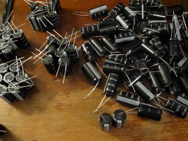
Wow; that's a super generous offer! It is funny; I just sat down to mess with this project again. Figured I could knock out another bag of capacitors while awaiting tungsten copper electrodes to show up in the mail tomorrow. Very curious how that material is going to machine. Almost dead set on drilling out the center of one electrode in each unit for the trigger wire... And of course the shape of the electrode "tip" should be rounded as well. I have setup my laser to cut borosilicate glass tubing, and need to get back to that at least to see how much I can improve on the process. I was doing six pretty slow rotations before, and it almost fell apart. I think if I do about 8 rotations it should cut the glass clean through. That doesn't mean it was the best method; but it sure did turn some heads in the laser cutting community when I mentioned it worked at all. That said; the tubing is actually kind of garbage in uniformity to begin with. Running it on the rotary has never allowed me to spin it on axis. The laser cuts as such, end up looking like garbage (sort of wide, and they might always look really bad). I expected the laser to simply score it, and was blown away when it actually fell apart at the cut line. I'm planning to run another batch quick before the electrodes arrive so I have something to play with. The only thing I'm concerned about still is the I.D. of the glass tubing. I may be well served to use the electrode diameter with a multiplier to build a better trigger tube (perhaps glass tubing with an I.D. 3 or 4x the electrode diameter). All of that remains to be seen once I test this new tungsten copper material. It's supposed to be ideal for spark gap switching. So... Mildly excited to see how much less it sprays all over the glass when the gas ionizes in the tube. Mmmm; plasma. Sadly. I misplaced my test projectile and haven't had the heart to make another one. That's because I already know it's not an ideal projectile in any way except one. The one being; it matches the weight of a 7.62x39 projectile; 123 grains, which is a useful benchmark. I'll find it, or grudgingly make a new one. @jtallen83I'll probably still take you up on your offer. But I do want to see how tomorrow's testing works out as a matter of proof. I do expect to be making a lot of replacement glass tubes if they continue to get spattered on with repeated firings. Even copper electrodes seem to last just fine; but the glass getting dirty was causing malfunction over time. Images: prepping the leads, and laying out piles of 7 for more strings/blocks to be soldered together again.
-
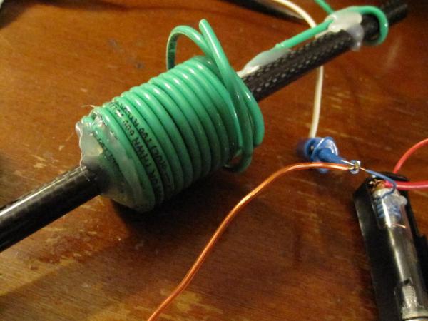
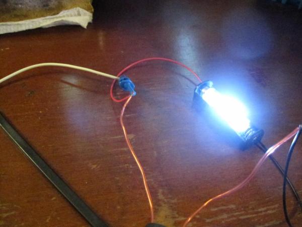
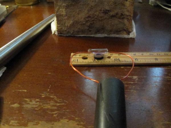
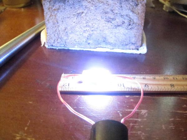
New 12ga wire coil wound on a carbon fiber barrel; just for testing. It's cheap, and using parts on hand. I was able to move the red coil to an acrylic barrel to see if there is any issue with eddy currents in CF. Might as well wind a few more coils if I'm going to start leveling up the power. Since the projectile is a set length; I can wind a 15ga coil from magnet wire I have; that will take some time. Those spark pictures are actually difficult to capture. I don't have a system for it; just keep trying. That particular installation makes a lot of ozone, and a sucking sound; but it's an early prototype of stainless steel screw electrodes. On the road to other materials if need be. AA battery holders are going to be garbage in terms of actual electrical contacts. Will need a slim nut, and a ring terminal on the screws to make that functional in real world testing. It's quite loose in a AA battery holder too which might be resolved with thicker glass tubing; or maybe larger I.D. too. Perhaps even better inside something much larger, like a 35mm film can sized container. They could last a lot longer if they didn't spackle the inside of the glass tube with metal particles. This particular tigatron model is up for testing with a shorter glass tube; among others. Quite frankly the old style with copper electrodes worked GREAT for the first 5 firings or so. They are really cheap, and quick to make. Just hoping for something a bit longer lasting as I step up the power. The next set of tests I will paint on some corona dope inside both ends of the glass tube leaving an inspection window in the middle. I'd rather not dope the whole thing if I don't need to. Can't lie. The sound of those huge ignition sparks (~20mm gap) really do get me going. The simple design will also allow it to just run the ignition HV generator on trigger pull. So with an empty capacitor bank, or a filled bank out of circuit; one can set off the loud lightning sounds "to make sure the gun is working". The spark picture in the middle is just that... An ignition spark. The full load flash that follows the ignition lightning is blindingly bright.
-
Killed my first trigatron tube with about 20 shots. It appears the metal spray on the glass is a problem, but after doing a little bit of searching I found a material that might be better than copper. Tungsten copper is apparently used in spark switch electrodes, and isn't terribly expense in 1/4" rods. Soldered up a lot of capacitors and found a potential error in my earlier line of thinking. I was doing napkin math and kept getting strange numbers; only once I "fixed" that problem did I realize I might have an efficiency issue or worse. That lead to me refactoring for a second day of soldering capacitors together. This time they are left to right backwards. That will give me the ability to bend if I need to make dramatic changes to my build here... Not a big deal; and I'm glad I caught it early on. I had the opportunity to speak with someone about my endeavors in this project. Discussing the original polish video briefly lead me to a potential "discovery" about that setup. It remains to be tested experimentally; but the above changes to the capacitor banks (left to right backwards) are a result of that conversation. The only other thing I have on my mind at this point is blowing up the cheap trigatron tubes. Literally. I'm worried about shattered glass or worse on a first firing when I upgrade to these larger capacitor banks. I also need a faster way to charge them; but for the time being I'm still covered if I take time between tests. From here on out experimental shots will happen outdoors. Might even wear some leather and a welding mask if it is looking risky. The flash inside the tube was already bright enough to make a dark shade useful. I'll check back in within a week. It's going to be fun testing these out; but I'm getting more nervous now. Just one swipe of bare skin on bare wires could be a problem. Every move around this needs to be calculated and methodical. Don't trip and fall face first into a charged capacitor bank.


-
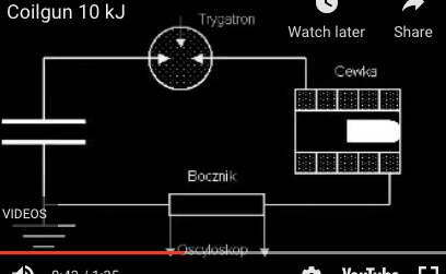
Found this video by accident. It's not really a rail gun, it is in fact what appears to be a multi-stage reluctance launcher. The only place I could find discussion of the mystery polish video in the first post of this thread was here: https://4hv.org/e107_plugins/forum/forum_viewtopic.php?id=151070 Nobody there seemed to have any idea what was going on either; or how it could function. So; I ran some more tests with the early parts I had on hand. So far; nothing groundbreaking. Though; the trigatron fires reliably, and drains the capacitor bank almost completely. Still experimenting with projectile insertion distance. It can make a huge difference in a single stage setup. There is again some metal spray on the glass tube after operation; and it might even show glass cracking after multiple uses. Think it might be wise to order thicker wall tubing for the next set of parts. Changing electrode material (to stainless steel maybe?) might also make that better. I'm not seeing any spray from the small wires on the HV trigger. Can't tell if the solder is helpful or not. Maybe it melts instead of sprays? I can make more of these at will with parts on hand; so it's not an issue to experiment further. Next up is to mess with other projectile materials. Aluminum isn't even special; interestingly GMX projectiles made of gilding metal have almost the same electrical resistance as aluminum. Nothing close to pure copper, but worth testing as an analog to the aluminum projectile used in the "unknown" video. Just upgraded the test capacitors from 2Series4Parallel setup at 600V (shown in the picture), to 3Series3Parallel at 900V. From here on out; it's going to be a fun game chasing safe working voltages. The next bank will probably be around 2kV. Then 4kV; and whatever I feel comfortable with beyond that. At some point; it becomes difficult to keep things from randomly arcing over in air, or to the end user. These capacitors are actually rated at 330V; but I have trouble charging up that last little bit, so I'm derating them in use for the time being. I can actually go a bit further derating max voltage and get much faster charging times as well. Shouldn't take too long to solder up a bunch of larger capacitor banks. Anticipate breaking the 2kV and 4kV barriers in the next few days. At some point I'll be able to start looking at projectile speed as well, and begin to consider specific limitations. So far so good though; and it's really neat to watch the "pop" inside the glass tube. I have been thinking about doping the inside of the glass with corona dope, which is a purple color. The portable build is going to require light shielding as an option for sure. It's blindingly bright with an air filled tube. Not yet sure how that changes if I switch to pure argon.


-
Why is nobody talking about apps for tablets? With either an iPad or Android tablet, there are apps for cats that actually react to touch as well. I tried the fish one for a while (makes water sounds too), but it wasn't as fun as other forms of stimulus. Not sure what kind of screen protector is even valid at that point; but an iPad bare glass is pretty hard. Maybe you all are right though; best not to get pets too interested in that kind of display... Probably doesn't end well. Isn't the great old outdoors better (not around here... hawks, fishers, owls, etc. will wreck small game)?
-
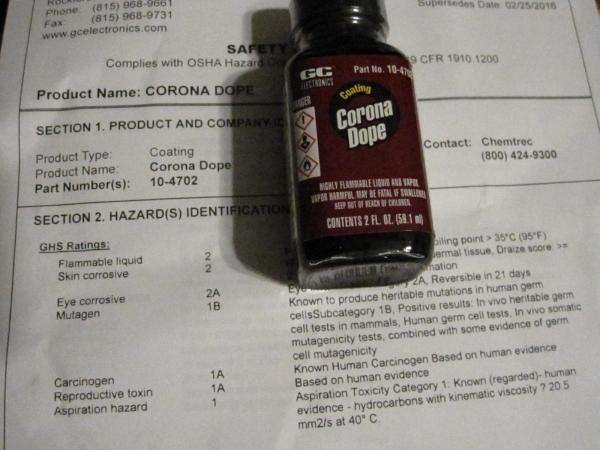
Feed it? You don't even need to go half that distance. A little sniff, or wiping it on your hands is a pretty good start. Was a lot more curious myself what kind of heritable mutations might be considered useful these days for humans. The MSDS doesn't say shiit about bat mutations; I assume it's only a problem for humans. Just doing a little more CAD sketching on this project. I've realized pretty quick that I'm only going to be able to have "fun" with this if I split things off now. There is no way the original design is going to do too much. Reading a lot more research from the 80s, 90s, and beyond has me pretty well sold on induction drive anyway. No contest in terms of efficiency; and it's a good primer for some other things I've been ignoring around here lately. What I want to be able to reproduce first; is the Trigatron firing of a ferromagnetic projectile, and ones of aluminum, and copper. With the same design shown in the video in the first post of this thread. I understand how that works, and the difference between steel and aluminum is what has me still wondering... That was a big part of starting this quest. I'll post up a bunch more research next time around. Still reading a lot of prior work to help (hopefully) avoid wasting time and resources on things I already know aren't great in terms of overall efficiency. At the same time. I want to test all my initial projectiles and coils as a baseline for corona discharge switching. Nothing wasted.

-
Hey. I want your 50 Beowulf. I have reloading dies... Building one. I might take something else too. Do you still have the two?
-
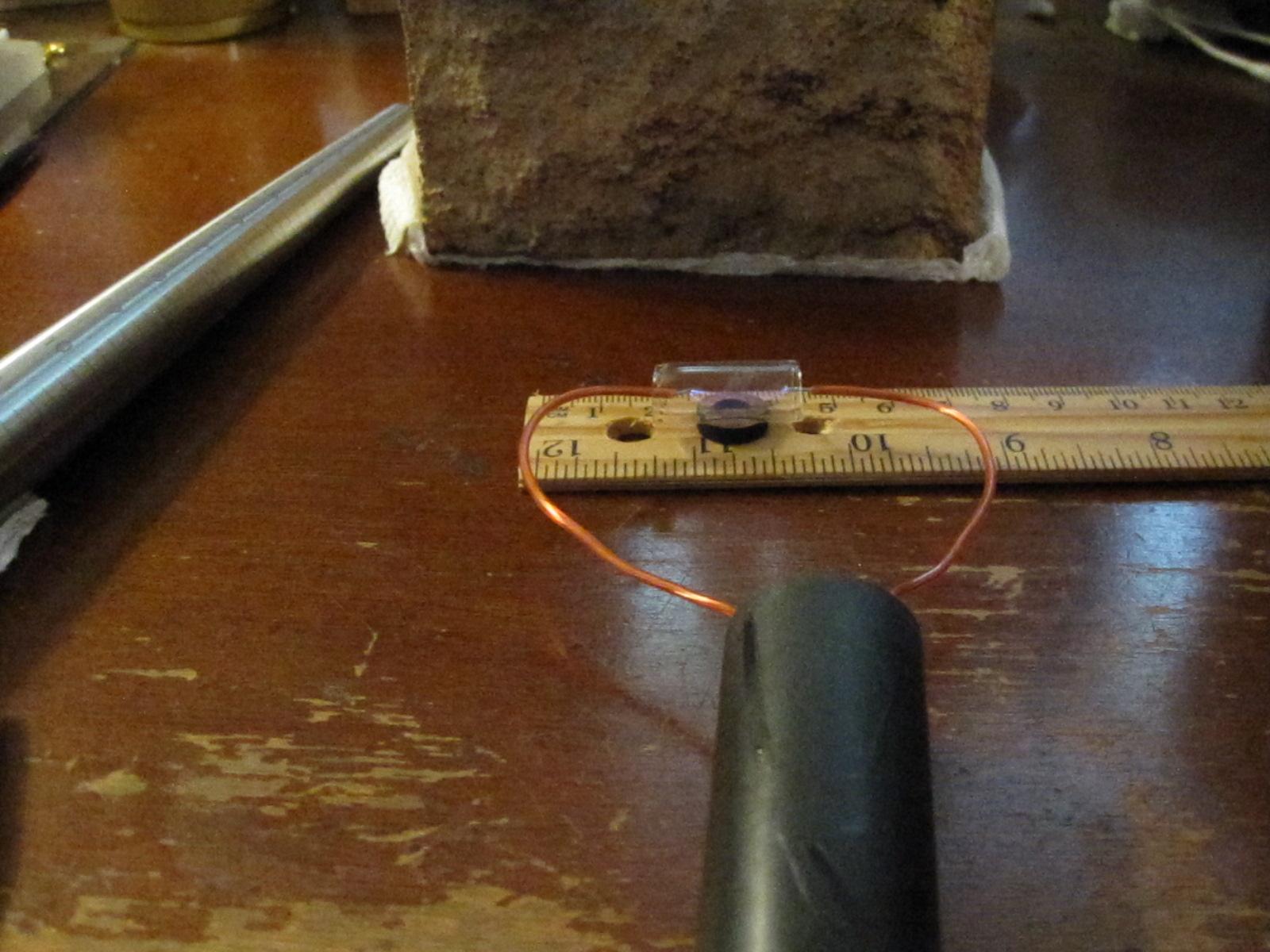
Been bouncing back and forth in my mind between the magnetic accelerator, and and some kind of combustion light gas gun. Made some decisions about which way to go on the lightning gun build, and acquired a few more parts. High voltage generators around 20kV, and some standard Corona Dope which is just a few hundred V/mil lower in breakdown voltage than the Super Corona Dope. I figured if I design for the lesser, using Super Corona Dope later would be even safer. I've never gotten a thick MSDS in the mail with a chemical before (usually have to download my own). This one is pretty serious though; really love working with mutagens. The last thing that appears to be missing here is a high voltage probe so I can actually measure the voltages I'm working with (for both design constraints and safety purposes), as well as use a scope to watch the timing of the same very high voltages. Looked at some brief napkin calculations for the combustion light gas gun. It seems like it wouldn't be terribly difficult to get rifle projectile energy out of a rifle sized package. The gas volumes required are small enough to work around one way or another. The really tricky part here is the unpressurized autoignition temperature of around 1,000F. Still not sure exactly how much that changes under compression, or what I can get away with in the real world. Did the first laser cutting on glass tubes in the rotary. Confining a spark inside one with open ends is LOUD (spark gap is easily 15mm long). I'm going to seal them when I install the other electrodes, but I'm quite certain they won't be silent. Looking forward to hooking things back up for a controlled discharge into the original high current red acceleration coil. Shouldn't take long to knock out some plug ends for the electrodes to mount to, and seal them up. The other circuit plugs into the same glass tube, using it as a switch to fire the coil. The capacitor charge rides the lightning from the HV discharge inside the tube, firing a short pulse to the acceleration coil. This is starting to look like fun again.

-
The first time I heard this song was on a Sony Walkman in my bed as a child. Tuning around the radio and finding this; it moved me. On the AM band no less. It was many years before I found out what it really was. It's how I feel right now though. Much more so powerful now even than it was back then... Things have changed. I'm ready to ride like the wind for the most part. West... South West.
-
There is also a twist factor; which had to be factored into that length. Any "round" tube will twist a tiny amount with temperature. A long steel measuring tape has both length and twist to contend with. Sometimes the decimal place matters; other times. I wish I didn't care at all. Twist is a pretty big one though. Is that really a millionth of an inch?
-
The low level physics comment was in fact my personal experience. The point of doing those math problems at a low level is to (hopefully) show the student that just kicking a ball into space, or even trying to shoot it out of a gun is extremely difficult in terms of energy required. And that's only part of the story... The accelerations required are such that it can be difficult to keep things from being torn apart in the process as well. The same reason a light gas gun was only specified to launch building materials; human meat bags are totally out of the question. I tried to get a copy of the paper referenced on the previous link: "A Light Gas Gun System for Launching Building Material into Low Earth Orbit", but I could not find a copy that didn't require me to pay for it. Would simply visit a university library for something like that (even today); but I'm not even sure visitors are currently allowed. Before COVID I wouldn't have thought twice about dropping by for an afternoon of light reading, or browsing the journal archives. What I did find online was a nice breakdown from UTRON Inc. that details the history of some of John Hunter's work. It talks about both the earlier "Two Stage Light Gas Guns" (bottom of page 6-7), as well as "Jules Verne Launcher" (bottom of page 10-11). The latter is the larger 1.52 km barrel length with hydrogen side injection. The second attachment is a PowerPoint slideshow with some details about the UTRON Inc. combustion light gas gun which apparently functions. All in all; this was a fascinating distraction that made me explore some other work I wasn't fully aware of. One note in the first PDF that applies to the lightning gun: "Large coilguns theoretically require very high voltage operation and very fast switching". That's been pretty clear to me since the beginning here; hence the reason I'm chasing reliable means of controlled arc discharge. I didn't see a lot of other options that made sense economically or performance-wise. Some ideal parameters would be, electrodes that don't change in shape over time after repeated use, and a reliable delay between trigger operation and magnetic field peak in the acceleration coil. In the event of induction operation, it appears the same system could be left undamped, and ring enough to provide A/C drive. STA-witherspoonOct2000.pdf 6349KruczynskiDavid.pdf
-
Figured it was about time to circle back. I enjoyed the brief experiments into hydrogen combustion as a propellant option. What I found out in the process; is that it's actually rather common, and used in some extreme high power applications. There was even some talk years back about using it as a way to launch building materials into space. The appropriate search term for such things is "light-gas gun", or "combustion light-gas gun" depending on the details. What I was most surprised by, is that light-gas guns have evolved into two stage affairs for the most part. Here is a quick write up of that which used to be hosted by the NASA Ames Research Center: https://space.nss.org/settlement/nasa/Nowicki/SPBI108.HTM That diagram is shown below. There is in fact no combustion of the hydrogen, it is simply used as a compressed gas to increase the speed of sound in the medium; thus allow for faster projectiles. ----------------------------------------------- There are a few things holding me back on the lighting gun build at the moment. First and foremost would be: finish reading technical documents (bunch of PDFs) posted a few days ago, and then doing a bunch more math to solidify my coil designs. All my work up to this point was running estimates to fit the rough design parameters. Now that I've modified the projectile shape a few more times; and perhaps material, I need to revisit all those calculations with a bit more precisions. Measurements of the appropriate coil length (number of turns per layer) is now possible. Then trying to maximize efficiency (number of coil layers, spacing, etc.); and then ensure that appropriate potting method will hold up under voltage as well as compression pressure that happens during firing. A few posts back there were a bunch of images of chemical options posted. The Super Corona Dope has the highest dielectric rating of anything, but it happens to be a varnish. I'm not at all sure how that would work for fully potting a coil. I'm a bit frustrated that I can't try it out for "cheap" either. A 2 fl oz jar is $20; and 33 fl oz is a little less than $80 shipped to my door. Seems like a huge waste to buy 2 oz and find out it will actually work for fully potting. On the other hand. If I can only use it as a thin coating; then I'll still need the epoxy potting material I would still be around the same $80 total. I MIGHT know someone with a jar of Corona Dope from yesteryear and that would certainly help in determining which way to go. Finally; I need to get the lathe out and start turning a handful of projectiles in steel and aluminum. Unfortunately I can't get that kind of dirty until I get some other work out of the way around here. There is still an outstanding question about induction vs. reluctance that I won't really be able to answer without hands on testing. I can use old or junk coils for that work; but I still need a bunch of projectiles to see which way I ultimately need to go. That may also impact some of the minor details in coil designs as well, so; everything needs to happen in order. I do already have a number of fairly large induction drive units; so testing can happen when I get to that point.
-
I presented the recipe. NY and CA are almost the same place if you live in America. Only a few gas station fill ups between us; just drive and drive and drive. Heard there was shooting fun in Nov. I'm working towards a sick trunk full of LOL. NY style.
-
This goes BOOM! It is also the same trigger method I'm using in the lightning build (for trigatrons). Might have to run these builds side-by-side actually. The hydrogen fuel is working right out of the gate. Love the fact that it's just LOUD! Not sure I'd trust it in a carbon fiber barrel. Only one way to find out though... Don't forget to wear your safety glasses every time.
-
Seems like there's a glitch with the forum. I tried to edit the last post because the videos didn't seem to work. In edit mode; they showed video players. But I was too late to try an updated post. These links should work for those videos; for at least a day or two. https://file.io/PS7aFobIC72A https://file.io/d55oCTUDvE9V